Key Takeaways
-
Stranded copper cable has 20-50% more insertion loss than solid-conductor cable, so use stranded cable only for short patch cords and solid cable for long permanent wall runs.
-
Test copper links across their full frequency range (Cat5e: 1-100 MHz, Cat6: 1-250 MHz, Cat6A: 1-500 MHz) rather than single points, and verify you are using the correct standard limits to avoid false failures.
-
When a link fails attenuation testing, follow a diagnostic process: confirm test setup, verify link details, clean connectors, inspect terminations, and use OTDR on fiber before replacing parts.
-
Multimode fiber loses only 0.3 dB over 100 meters (~3% signal power) while Cat6A copper loses 12 dB over the same distance (~94% signal power), making fiber superior for long-distance runs.
-
Common preventable causes of high attenuation include dirty fiber connectors, poor terminations at jacks and patch panels, cable runs exceeding length limits, and stranded cable in long permanent installations.
-
Signal loss in cabling can cause hidden problems in VoIP phones, security cameras, and access control systems that appear unrelated to network infrastructure, so certification and proper design prevent troubleshooting guesswork.
Have you ever had a network that looked perfect on paper but still acted up? Phones cut out. Cameras froze. Files crawled across the office. If your cabling checked out on install day, hidden signal loss could be the culprit. That signal loss has a name, and it matters more than most people realize.
Attenuation in structured cabling is the drop in signal strength as data travels through a cable. Think of shouting across a big room. The farther the sound travels, the weaker it gets. Cables work the same way. Some loss is normal, but too much can break a connection.
In this guide, we will keep things simple and friendly. You will learn what attenuation is, what causes it, how pros test it, and what to do when a link fails. Whether you run a small shop, manage an office, or oversee IT for many sites, you will walk away with clear, useful steps.
What Is Attenuation in Structured Cabling?
Attenuation is the reduction in signal power as it moves through a cabling link. It is measured in decibels (dB). The lower the number, the better the link.
You will often hear the term “insertion loss” today. In current standards and field testing, insertion loss is the preferred name. For everyday talk, the two terms mean nearly the same thing. If a tester says your link has too much insertion loss, it is telling you the signal is fading too much.
Why does this matter to a business? Your structured cabling carries your phones, internet, security cameras, and more. If the signal fades too much, gear may slow down, drop packets, or stop linking at all. That means dropped calls and choppy video.
Attenuation vs. Insertion Loss
Here is the quick answer. Attenuation is the general idea of signal loss. Insertion loss is the modern testing term for measuring that loss across a full link. Most pros use them interchangeably, but standards and testers lean on “insertion loss.”
Why Signal Loss Happens in Copper and Fiber
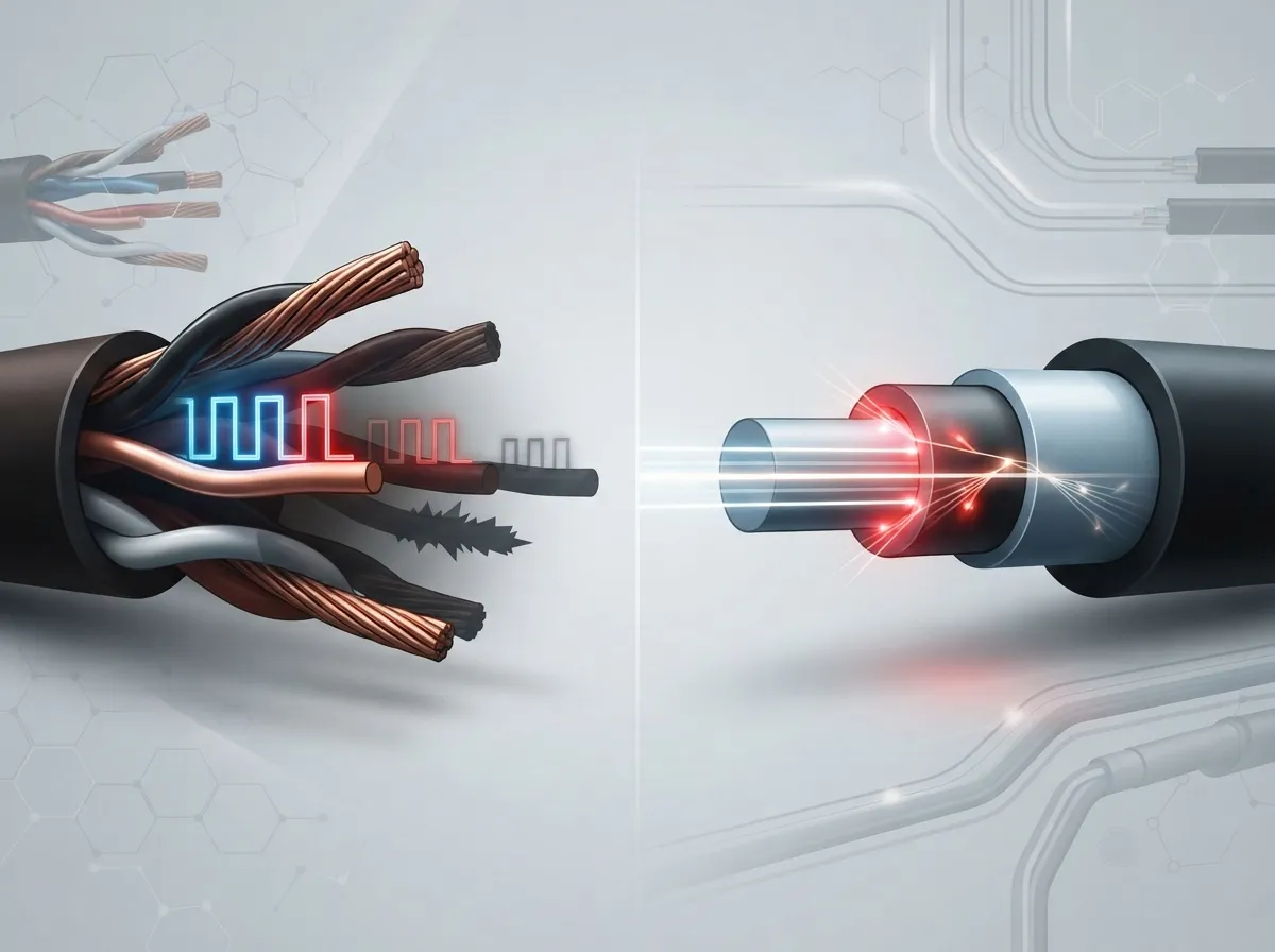
Every cable loses some signal. That is just physics. The trouble starts when loss climbs too high for the network gear to handle.
Loss shows up in both copper and fiber, but the causes differ a bit. Length matters in both. The longer the run, the more signal you lose.
Copper Cable Loss
For copper Ethernet, loss depends on several things. It changes with frequency, so faster speeds put more stress on the cable. It also depends on conductor size, cable build, and temperature.
Common copper trouble spots include:
- Runs that go past the length limit
- Poor terminations at jacks and patch panels
- Undersized conductors
- Stranded cable used in long permanent runs
- Hot spaces like ceilings that trap heat
- Damaged or wet cable
Here is a fun fact that surprises people. Stranded copper cable can have roughly 20 to 50 percent more insertion loss than solid-conductor cable. That is why stranded cable belongs in short patch cords, not long wall runs.
Fiber Cable Loss
Fiber loses signal too, just in different ways. Loss builds up from the fiber itself, plus every connector and splice along the path. A dirty connector can cause big trouble all by itself.
Common fiber trouble spots include:
- Dirty or damaged connector end faces
- Poor connector alignment or termination
- Tight bends in the cable
- Damaged cable
- Extra connectors or splices nobody planned for
Contamination is a favorite culprit. A tiny bit of dust on a connector can cause loss you could have avoided with a quick cleaning.
Copper vs. Fiber: A Quick Comparison
Both cable types lose signal, but not in the same amounts. A well-known example from Fluke Networks shows the gap. Over 100 meters, multimode fiber loses about 0.3 dB, which is roughly 3 percent of signal power. Category 6A copper loses about 12 dB over the same distance, roughly 94 percent of signal power. This is an example, not a rule for every cable, but it shows why fiber shines on long runs.
| Factor | Copper (Ethernet) | Fiber Optic |
|---|---|---|
| Main loss drivers | Length, frequency, conductor gauge, temperature | Length, connectors, splices, bends, dirt |
| Common problem | Poor terminations, stranded cable in long runs | Dirty or damaged connector end faces |
| How loss is judged | Across a frequency range for the cable category | Against a total link loss budget |
| Temperature effect | Loss rises as heat rises | Little effect from normal room heat |
| Best fit | Desk drops and shorter runs | Backbones and longer distances |
If you are weighing the two for a project, our guide on copper vs fiber cabling walks through the tradeoffs in plain language.
How Copper Attenuation Is Tested
Copper links are certified with a field cable certifier. This tool tests the link against the standard for its category. For attenuation in structured cabling, the tester measures insertion loss across a whole range of frequencies, not just one point.
The test range depends on the cable category:
- Category 5e is tested from 1 to 100 MHz
- Category 6 is tested from 1 to 250 MHz
- Category 6A is tested from 1 to 500 MHz
Always use the current limits built into your tester and the standard you selected. Picking the wrong test limit is a common reason for confusing results.
If you are deciding between categories, these two reads can help: 7 Key Differences Between CAT5e and CAT6 Cabling for Tampa Businesses and How to Choose Between Cat6 and Cat6A for Your Office.
How Fiber Attenuation Is Tested
Fiber testing works a little differently. Instead of a frequency sweep, installers check the link against a loss budget. That budget adds up all the expected loss in the link.
A common planning formula looks like this:
Total link loss = fiber attenuation coefficient × length + connector losses + splice losses
The applicable standard and the network application set the pass limit. Here are some published numbers to give you a feel for it. These come from a Corning guide that references TIA-568.3-D. Always check the standard edition and product specs for your own project.
| Fiber Type | Wavelength | Maximum Attenuation Coefficient |
|---|---|---|
| Multimode OM3/OM4 | 850 nm | 3.0 dB/km |
| Multimode OM3/OM4 | 1300 nm | 1.5 dB/km |
| Multimode OM1/OM2 | 850 nm | 3.5 dB/km |
| Multimode OM1/OM2 | 1300 nm | 1.5 dB/km |
| Single-mode (inside plant) | 1310 and 1550 nm | 1.0 dB/km |
| Single-mode (outside plant) | 1310 and 1550 nm | 0.4 to 0.5 dB/km |
Remember, these are fiber coefficients, not full-link pass limits. A commonly cited maximum for a connector pair is 0.75 dB, but your project spec may set different requirements.
Tier 1 and OTDR Testing
Fiber Tier 1 certification uses an Optical Loss Test Set, often called an OLTS. It measures end-to-end loss for the whole link. It tells you whether the link passes, which is the big question.
An OTDR is a different tool. It helps you find and describe individual events along the fiber, like bends, breaks, connectors, and splices. Think of the OLTS as the report card and the OTDR as the detective. If you want to plan your own fiber work, see how to choose fiber cabling for your business network.
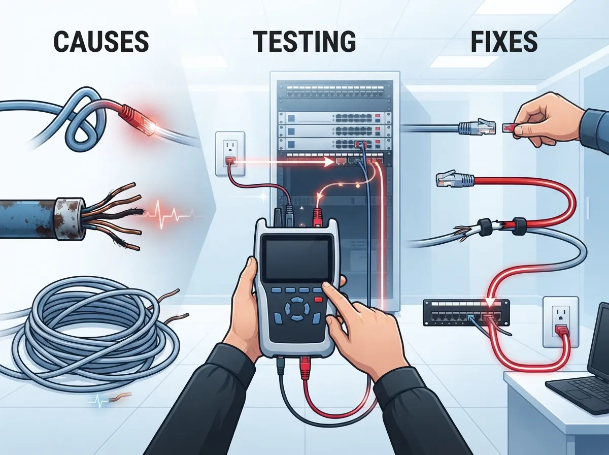
What To Do When a Link Fails
A failed loss test can feel stressful, but there is a smart way to handle it. The worst move is to swap parts at random. That wastes time and money. Follow a clear process instead.
- Confirm the test setup. Make sure you picked the right standard and test limit for the link.
- Check the link details. Verify the length and topology match what you expect.
- Review test cords and reference method. Bad or worn test cords can cause false failures.
- Clean the connectors. Dirt is a top cause of avoidable fiber loss, so clean before you retest.
- Inspect terminations. Look for poor work at jacks, patch panels, and connectors.
- Use an OTDR on fiber. If you still need answers, locate the exact event that is causing loss.
- Fix the cause and retest. Repair the actual problem, then certify the link again.
This step-by-step habit saves teams a lot of headaches. It also keeps your records clean, which helps if you ever need to prove the work met spec.
Easy Ways to Reduce Attenuation
The best fix is to prevent the problem from the start. A little planning goes a long way. Here are simple habits that keep loss low:
- Stay within length limits when you design each run
- Use solid cable for long permanent links and stranded cable for short patch cords
- Pick the right category or fiber type for your speed needs
- Keep the number of connectors and splices as low as makes sense
- Clean and inspect fiber connectors before every connection
- Respect bend radius rules during install
- Keep cable out of hot, wet, or high-risk areas when possible
- Certify every link and keep the test reports
Planning ahead pays off. If you are mapping out a new build or upgrade, take a look at how to plan network cabling installation in Tampa Bay. And if you are wondering how many things can go wrong without a plan, 12 Structured Cabling Mistakes That Hurt Your Business is a helpful read.
Why This Matters for Phones, Cameras, and Access Control
Your cabling does more than carry internet. It also feeds VoIP phones, security cameras, and door access systems. Weak links in the cabling can show up as strange problems in these systems.
A choppy call might not be a phone problem at all. A camera that keeps dropping might not be a camera problem. Sometimes the real issue is signal loss hiding in the wall. Solid cabling gives every one of these systems a stable base. To see how it all connects, read 13 Ways Structured Cabling Supports VoIP & Cameras.
Sometimes slow speeds trace back to the line coming into the building instead. If your problems seem to start outside your walls, check with your Internet Service Provider too. Our post on why business internet is so slow and how to fix it can help you sort out where the trouble lives.
Should You DIY or Call a Pro?
Small jobs may tempt you to grab a crimper and go. But certification takes special tools and know-how. Without a proper tester, you are guessing about attenuation. Bad terminations can pass a simple continuity check and still fail a real loss test.
Professional installers test each link against the right standard and hand you the results. That paperwork gives you confidence and protects your investment. If you are on the fence, DIY vs. Professional Cabling: Which Is Right for Tampa Offices? lays out the pros and cons.
Ideal Solutions Provider has spent over 24 years helping businesses get cabling right. As a single point of contact, the team handles design, install, testing, and support, so you do not have to juggle vendors. You can learn more about their structured cabling services or see how they approach professional structured cabling for Tampa businesses.
Wrapping It Up
Attenuation in structured cabling is simply signal fading as it travels. A little is normal, and a lot is trouble. Length, connectors, bends, dirt, heat, and poor terminations all play a role. The good news is that careful design, clean connections, and proper certification keep loss under control.
Remember the big ideas. Use insertion loss as your testing term. Certify copper across its frequency range. Check fiber against a loss budget. And when a link fails, diagnose before you replace anything.
Ready to make sure your network is built on solid ground? Contact us for a free consultation, or call us to talk with a real person who can help. We would love to help your business run smoothly. You can also follow along with tips on YouTube, Facebook, and Instagram.
FAQs
Q: What does attenuation mean in structured cabling?
A: Attenuation is the loss of signal strength as data travels through a cable, measured in decibels (dB). A little loss is normal, but too much can slow your network or break a connection. Lower numbers mean a healthier link.
Q: What is the difference between attenuation and insertion loss?
A: They describe nearly the same thing. Attenuation is the general idea of signal loss, while insertion loss is the preferred term in current standards and field testing. Most pros use the two words interchangeably.
Q: What causes high signal loss in copper and fiber cabling?
A: In copper, common causes include long runs, poor terminations, undersized conductors, heat, and damaged cable. In fiber, look for dirty connectors, tight bends, bad terminations, and extra connectors or splices. Cleaning and careful install work prevent many of these issues.
Q: How do you troubleshoot a link that fails an insertion loss test?
A: Start by checking the test standard, link length, test cords, and reference method. Then clean connectors and inspect terminations before retesting. On fiber, an OTDR can pinpoint exactly where the loss happens so you fix the real problem instead of guessing.